Yamaha Gauges Wiring Diagram
31 Yamaha Outboard Gauges Wiring Diagram Wiring Diagram List

Yamaha Gas Guage Wiring Wiring Diagram Online Library
Yamaha Fuel Management Wiring The Hull Truth Boating And
Yamaha Outboard Tach Wiring Wiring Diagrams Site
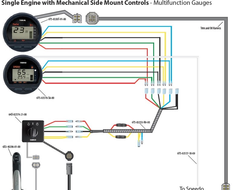
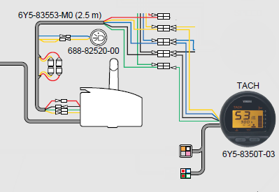
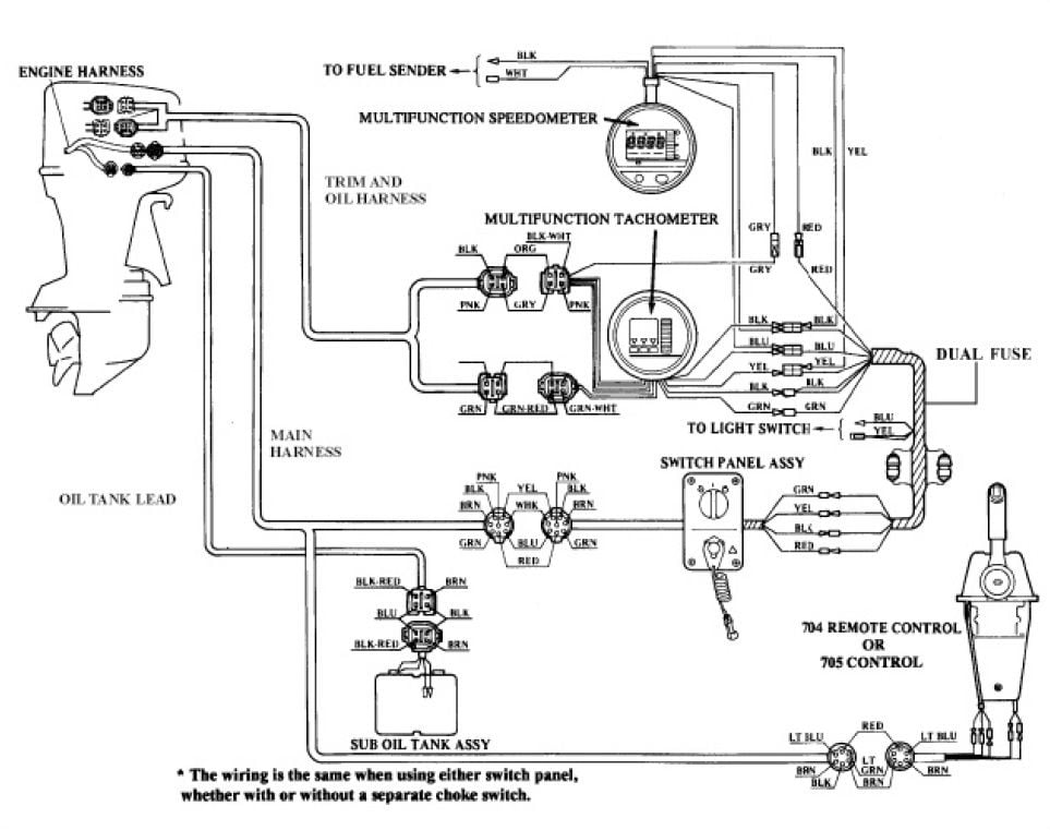
Yamaha Digital Multifunction Gauges No Tach Function Working

Yamaha 250 Outboard Gauge Wiring Wiring Diagrams Resources
Yamaha 115 outboard tachometer wiring diagram yamaha outboard analog tachometer wiring diagram yamaha outboard digital tach wiring diagram yamaha outboard fuel gauge wiring diagram yamaha outboard gauges wiring diagram yamaha outboard multifunction gauge wiring diagram yamaha outboard tachometer wiring diagram yamaha outboard trim.
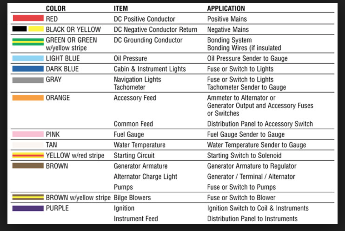
Yamaha gauges wiring diagram. For those running f20 to xf425 outboards genuine yamaha conventional digital gauges offer flexibility and streamlined rigging. There is an industry standard set of wire codes in general use by most manufacturers except yamaha. Here is a listing of common color codes for yamaha outboard motors. Colors listed here may vary with year model but in general should be a good guide when tracing yamaha wiring troubles.
You can download pdf files. Yamaha outboards are cooled by raw water with a bypass valve that opens when the cylinder head reaches a preset temperature. They also provide the ability to monitor several vital boat systems performance and trip stats when properly equipped. Yamaha outboard wiring diagram wire center.
I am looking for wiring diagrams for ignition and gauges for all of the yamaha digital display multi function gauges operate the same. 1 cylinder which permits the installation of a temperature gauge. Theres an accommodation for an analog sensor a boss in the top of the no. Yamaha outboard tilt and trim gauge wiring diagram wiring diagrams yamaha outboard gauges wiring diagram additionally wiring diagram gives you the time body in which the.
For determining the engine speed a component called a tachometer only. Yamaha outboard wiring diagram pdf collections of johnson outboard wiring diagram pdf wiring diagram collection. Yamaha trim gauge wiring diagram wiring diagram is a simplified within acceptable limits pictorial representation of an electrical circuitit shows the components of the circuit as simplified shapes and the knack and signal friends amid the devices.

Be 5943 Diagram Further Gauge Also Yamaha Fuel Management Gauge
Yamaha 250 Outboard Gauge Wiring Wiring Diagrams Resources
Yamaha Tachometer Wiring E26 Wiring Diagram

Ma 5523 Yamaha Digital Gauges Wiring Diagram

C0d9 Wiring Diagram Mercury To Yamaha 6y8 Gages Wiring Resources

Yamaha Marine Wiring Diagram Wiring Diagrams Resources

Teleflex Fuel Gauge Wiring Diagram Google Search Tachometer

Fuel Gauge Wiring Diagram Diagram Fuel Gauges
Wiring Diagram For Yamaha Command Link Tachometer Kit Bloodydecks
1998 Yamaha Outboard 150hp Salt Water Series Ii S150txrw Gauges

3e2 Trip Gas Gauge Wiring Diagram Yamaha Wiring Library

Yamaha Gas Guage Wiring Wiring Diagram Online Library

Yamaha 250 Outboard Gauge Wiring Wiring Diagrams Resources

For Aw Wiring Diagram For A Set 75 Hp Yamaha I Do Not Know What
